Ihave always thought that using an oscilloscope to display something other than your typical wave forms was kind of interesting. One the first instances of it I ever saw was on the Synertek SYM-1. It was a single board 6502 computer released in 1978. It had the ability to display text on your oscilloscope. This was the first computer that I ever owned (purchased in the early 80’s) and I still have it stored somewhere. Back then however I didn’t have access to an oscilloscope so have never actually seen it in action. One of the other interesting things I have seen was to display an analog or digital clock face on the scopes screen.
Over the years I have seen a few related projects like this one but I have not ever got around to building one. However a while back I ran into a posting in one of the EEV Blog forums that used an ESP32 module with it’s 2 internal DACs to generate the X-Y signals needed to display the clock face. It uses it’s Wi-Fi connectivity to use NTP to get accurate time. The project is really simple as it just needs a ESP32 module and a couple of BNC connectors. You can find more details at the designers GitHub site: https://github.com/maurohh/ESP32_OscilloscopeClock. So I decided to build one.
 Once I decided to build this I went out to get the parts. Luckily in Vancouver we have a couple of decent hobbyist electronics parts stores. I went out to Lees Electronics to get what I needed. All that I required was the ESP32 module and a couple of PCB mount BNC connectors. I had a protoboard PCB and some header strips kicking around so I did not need to buy those.
 For projects like this I don’t usually bother with a case and find that using a protoboard works fine. One issue is that the protoboard is so light weight that the cables tend to pull it around and eventually it gets broken. I find that mounting it on a small piece of plywood gives it more stability and this combination gives a inexpensive but decent way to mount projects. It works fine for projects that will stay inside and don’t need to get handled much. This project doesn’t need a power switch and I planned to power it from the ESP32 modules USB port from on old cell phone charger.
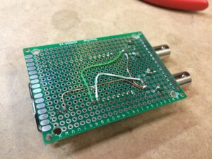
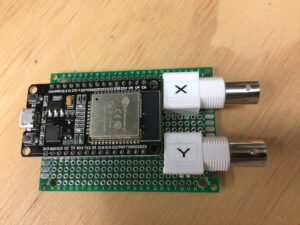
 The build was very easy, the BNC connectors required the most work as their mounting tabs required drilling larger holes in the protoboard. I used some #24 wire (from some solid Cat5 cable scraps) and some #20 copper to make the few required connections on the bottom of the board. I used some header sockets on the top of the board to mount the ESP32 module. This allows me to remove the ESP32 module (the most expensive part of the project) to reuse in another project should I want to in the future. I like to use the smallest sized protoboard possible to make a compact sized project. As you can see you end up with a compact finished product that for me seems to stand up to handling.
Once the hardware was finished it was time to work on the software. It’s more work (for me anyways) than the hardware. While you can complain about the Arduino IDE you have to like it’s flexibility. The first thing you need to do is add ESP32 support to it. You can find decent instructions about doing so here: https://github.com/SensorsIot/arduino-esp32 .
Once you get the ESP32 support added, you will be able to compile the code. However I ran into a problem, the code would get a compile error complaining that it could not find “ESP8266WiFi.h”. This line located in the NTPtimeESP.h file as “#include “. Looking around the code it appears it was perhaps based on some previous ESP8266 code. The ESP32 code I looked at seemed to reference “WiFi.h” instead. So if you have the same issue, open up the “NTPtimeESP.h” inside the NTP library and replace the “#include ” with “#include “. Note you will only have this issue if you use the NTP library but it’s the only way to ensure that the clock stays correct as the ESP32 doesn’t have a real time clock (RTC)
Once you can get the code compiled the next hurdle is setting the time zone. The NTP library used doesn’t have a lot of information on the the various settings but I did eventually determine that you needed to modify the “NTPch.getNTPtime(1.0, 1);” request. Simply change the first argument with your required GMT offset. So for me in the Pacific Coastal Zone (GMT -8), I changed “NTPch.getNTPtime(1.0, 1);” to “NTPch.getNTPtime(-8.0, 1);” . You can determine you time zone offset at this site: https://en.wikipedia.org/wiki/List_of_UTC_time_offsets.
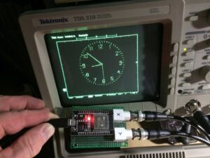
 After this you should be good and able to get the display on your scope. Your scope will need to support X-Y inputs (not all do) and either analog or high end digital scopes will give the best image. I have an old digital scope and the display is a bit chunky and strobey but certainly readable.
